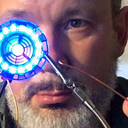
A Simplified Build for the Beating LED Heart

Jiri Praus’s sculptures are beautiful and inspiring. For Mother’s Day I wanted to make my wife an LED heart that pulses to the holder’s heart beat. Unfortunately, I lack two things that Jiri has — skill and talent. Undaunted, I cobbled together a rough facsimile that required less complex electronics, more suited to my limited skill. And while my work wasn’t as pretty as Jiri’s work, I was able to build it. I made a few mistakes along the way, but here’s what I learned.
My biggest change was using an Adafruit Feather M0 instead of the Arduino Nano that Jiri used (I used the Bluefruit LE model of the Feather, although I haven’t yet incorporated Bluetooth into the build). The Feather M0 board is small enough for the build, but has pass-through charging, and an on-off switch can be easily wired directly to the frame, eliminating the need for two components — the LiPo Battery charger and the Micro USB breakout board (I also could skip the desoldering, something I’ve never been good at). If you have skill — follow Jiri’s beautiful design or use one of the variants he suggests in his Instructable. But if you’re clumsy like me, or want fewer components in the build, consider using the simplified design with fewer components.

First — you can follow Jiri’s original build at his Instructables page for this project. Also consider supporting Jiri Praus on Patreon. He does truly amazing and inspiring work, and I’ve learned a lot following his builds.
I printed the 3D template for the heart sculpture as per Jiri’s design (I used a service since I don’t have my own 3D printer. Many libraries also offer 3D printing for a low cost).
I used this brass wire bought from Amazon. I snipped it off in about 1.5 ft. lengths, then straightened it by grabbing separate ends of each wire with a pair of pliers and pulling hard, twisting slightly while pulling. This provided enough tension to straighten out the wire. I then cut smaller pieces from the straight wire, as needed.
Next, when soldering I found that the double-sided tape technique that Jiri used didn’t work for me. The brass wires kept separating from the tape — likely because I’m not as fast and nimble at soldering. I kept melting the adhesive and the wires would slip off. Instead, I used blue fun tak wall tacking to temporarily attach brass wire segments to the 3D template. A sticky glue like Sugru is too sticky, but fun tak is really easy to position, holds well through soldering, and cleans up easily with alcohol wipes.

You’ll solder up one side of the sculpture frame at a time. Pay attention to where you finish one side so you don’t overextend your sculpture to the other half, or have a side that is incomplete. If you solder beyond the half-way point you won’t be able to remove the sculpture from the 3D printed template.
Also, definitely use solder flux & the kind of 3mm solder tip Jiri recommends (you can see it in action in his YouTube videos linked from his Instructable). I used Jiri’s technique of touching the tip to the solder, then touching the tip with liquid solder to the flux. The solder should flow over the flux and create a solid bond. Start with the bottom half of the heart sculpture so your technique can improve through practice and you’ll be better when completing the top half, later on. Even after practice, my soldering technique made my heart look like it was covered in thorns. I told my wife it symbolizes a love that was tough enough to endure life’s struggles. Pro tip: waxing poetic can make flaws seem romantic :)
Next, wire up the 9 LEDs to the heart frame that will go inside the sculpture. Jiri provides a printable paper template on his Instructables page, but I couldn’t get this to print in the correct dimensions. This is probably my profound inexperience, or maybe it was because I used American-sized 8.5" x 11" paper instead of Euro standards. I wasn’t sure what the 25 meant on Jiri’s drawing, and when I tried to set this to 25 mm, the sizing was still off. Instead I calibrated things myself and resized the image. You can find a .pdf of the template I resized in this Google Drive, but use Jiri’s if you know more than me and know how to properly print in the expected size. Also free free to use the comments in this post to correct my inability to print Jiri’s doc on my US printer, if you could get his template to properly print.
The little LEDs that you solder should be oriented with the diagonal notch in the upper left corner of the first LED when the LEDs are facing up (remember, you face them down when soldering). Look closely at Jiri’s images and you can make out the diagonal notch. I didnt even notice this at first and was confused how to position each LED. You can test that your orientation is correct and that your soldered connections are sound by testing the LEDs after each solder. Just connect the wiring to alligator clips, and clip the other end to jumper wires that you poke into the holes of your board. If you run your code at this point, the lights will light up red for a few seconds, then flash off since no sensor is attached.
Before soldering the LED frame, I found it useful to bend the wire into the shape that followed the printed paper template. I then covered the paper with clear double sided tape and pressed the bent brass wire onto double-sided tape so that it matched the shape on the printout. Then I placed something heavy on top of the wire so it didn’t pop off the tape, and I let it rest on the wire overnight. This helped the wire conform to the shape on the paper template, flattened it out, and helped to keep it’s shape when soldering. If you have precise skill in bending wire you may not need to do this, but again, I am not skilled.
Also, tin each of the pads on the LED with a bit of solder & do the same with the brass wire at the point where you’ll solder on the pads. Then you can add a bit of flux and should be able to more easily solder the wire and pads together. Take your time and take breaks if you need to. Make sure none of the solder touches other pads. The outer wire will be your ground, the inner wire will be your power, and the straight wire segments in between will carry the data signal. Double-sided tape seemed to hold the LEDs and heart shaped inner and outer wires well, but I used the blue fun-tak to hold the middle signal segments in place while soldering. These smaller brass signal segments run between LEDs wont rest on the page because they are to be soldered to the back of the LEDs, wo double aided tape on the page won’t belp.
This is delicate. After I soldered the heart frame to the bottom half of the sculpture, one of my data wires broke free of its solder and two lights went out. I tested it before final assembly, so I was able to carefully resolder the loose wire before sealing in the two halves of the sculpture.

I also didn’t wire the outer frame directly along the LED heart. My measurement wasn’t that precise. Instead I wired four brass legs coming out of the outer ground (and only the ground — don’t let the legs touch your inner power wire or the signal wire). This made it much easier to position the LED frame inside the sculpture frame, and I just had to solder these legs to the bottom half of the frame. I trimmed off any excess from these legs after soldering in the LED heart.
As mentioned, I used an Adafruit Feather M0 board because it was small enough for the sculpture, but still had pass-through charging. This means you can plug the battery into the board, but plug the board into a USB cable and charge it without having to add any additional electronics. This board also allows you to easily add an on-off switch by wiring a standard switch like this — one leg (either outer leg) to the En pin, the middle to ground, and the other pin on the three pin switch isnt attached to anything. I initially left the pins exposed and my build was shorting out when the metal pins touched the frame. I fixed this by covering the metal pins in MG Chemicals liquid connector coating, which holds better than electrical tape. I attached the on/off switch to the frame using super-glue after finding a segment that held the switch most snugly. The wiring diagram near the start of this document shows the wiring I used in my build.
If you choose a board other than the one Jiri or I used, be sure the board you choose will work with the libraries used in Jiri’s code. I mistakenly assumed the NeoPixelBus library used in this project would work with the first board I chose — an Adafruit Feather nrf52840, but that library wasn’t compatible (Adafruit didn’t write this library. It was written by the brilliant “Makuna” on GitHub — also consider supporting his work via the donate button on his GitHub page). You can find compatibility information under Supported Platforms on the NeoPixelBus page.
Be careful when wiring the sensor. They’re quite delicate. I’d suggest threading the wires up from the bottom instead of soldering them looping down from the top like I did. But if you use this technique, be careful not to touch any of the other board components while soldering or you can ruin the sensor board (I did this — fortunately I bought the boards in a two-pack on Amazon so I had a spare). Jiri’s build uses brass wire to hold the electronics to the sculpture and also to provide all of the electronics wiring in an elegant holding cage. I don’t have the skill to bend wire with such precision and was really worried that if I used this approach, my wires would touch and short out my project. Instead, I used standard wire. I used mostly black and red colored wire, since these matched the heart theme. If you use multiple wires of the same color, be absolutely sure to track that you are soldering the correct wire to the proper board pin or component or your sculpture won’t work.
Test everything along the way and especially before soldering the two halves of the sculpture together. Make sure you download the Adafruit board settings (see the Adafruit site, or other instructions for your specific board if you’ve never done this before). Then load up Jiri’s Arduino heartRate.ino sketch (linked in his Instructable). Also load any related libraries used in his sketch. Make sure components aren’t touching in ways that could short things out (e.g. nothing linking power & ground directly in the LED frame). Hopefully everything will work for you. If the sketch doesn’t load, make sure (simple things) your board is plugged in, your on/off switch is set to “on”, the Arduino IDE has proper board and port settings for your components, and that you’re using a board that’s compatible with Jiri’s code.
I attached the Feather to the frame of the sculpture by threading brass wires to the front and back mounting holes in the board. Using a wire that goes along and under the longest side of the board will provide a cage to hold the battery underneath (similar to Jiri’s design). I soldered the front mounts first, making sure the USB port was positioned so it could be accessed at the top of the heart. Be sure to keep the wires out of the way — you don’t want to burn any wires while soldering.
You don’t want to solder with a battery nearby. LiPo batteries are so flammable they can burn under water. You are on your own to learn and take all safety measures. I’m not responsible if your build causes an accident, damage, or injury. Make sure you’ve got enough room to slide the battery in when you’re done soldering and things have cooled. The brass wires that span the bottom of the board can be pushed by hand to keep the battery in place after you slide it in. Just leave yourself enough room to fit the battery in. Be sure to test the fit before soldering, as space is tight.
Finally (and carefully, since you’ve got your battery and electronics in the sculpture now), you can seal the connections of the two halves of the heart sculpture. Always push that battary as far away as it’ll go from anything hot. DO NOT SOLDER NEAR THE BATTARY. Charge up your battery and if your sketch is loaded, your heart should work great.
I’ll likely create newer versions of this heart as my skill improves and if I do, I’ll be sure to add a build video to my YouTube channel. My wife really liked the heart’s light and asked for it to have an always-on mode so it could be used like a mood light, sort of like a candle. For a future build I’ll likely create a stand that charges the heart and holds it while in the to-be-added night light mode, and I’ll modify the code to support Adafruit’s Bluefruit app (making sure I use a Feather Bluefruit). The app has a color wheel for selecting colors and it should be possible to write code to allow user-selectable colors for thr LEDs. The keypad buttons on the app can be adapted for specificly programmed options like always on, pulse animation, etc. I used this app in a similar way when I created my CircuitPython Bluetooth-controlled Necktie. If you’re looking for a simpler project, or a school project to use with younger makers, the necktie is a good place for newbies to start. The build can be easily adapted to be embedded in a scarf or other garment, too.
Once again, thanks to Jiri Praus for such great inspiration and for sharing his designs, templates, and code (follow him on Twitter, Instagram, and YouTube and consider supporting him via Patreon).
If you found this useful, let me know, and if you have more tips, feel free to share (or correct my clumsy work).
Cheers!
Prof. John Gallaugher teaches Technology and Business at Boston College. All lectures for his Beginner to Full Stack Swift/iOS development course are available free on YouTube (it’s taught as a flipped class, with lectures online). Even though his soldering is clumsy and he lacks skill, he also teaches Physical Computing (think wearables, robots, Arduino, and Raspberry Pi). You’ll find videos for fun, step-by-step projects on his YouTube channel. He also writes one of the leading Information Systems Textbooks used in business schools worldwide. You can reach him on Twitter via: @gallaugher.